
Distribution Transformer of Class 35kV
Product model description
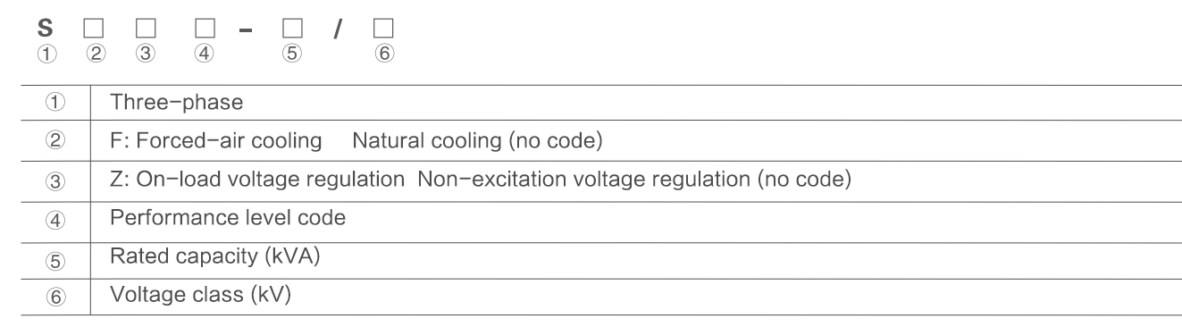
Product Overview
This product series features advanced design with significant improvements in materials, structure, and manufacturing processes. The high and low voltage clamping frames utilize steel tension bands or upper/side beams to form a robust framework, enhancing core clamping force and withstanding transportation impacts. With excellent short-circuit resistance, an aesthetically pleasing appearance, and reliable operation, these transformers deliver low losses and minimal noise, achieving performance levels comparable to advanced international products.
The prototype of our SZ11-8000/35 transformer successfully passed the sudden short-circuit test conducted by the National Transformer Testing Center in a single attempt. The high and low voltage windings incorporate longitudinal oil channels to optimize heat dissipation, significantly reducing the copper-oil temperature differential and hot-spot temperature rise within the windings.
Operating Conditions
1.Maximum ambient temperature: +40°C
2.Minimum ambient temperature: -25°C
3.Altitude:<1000m
4.Maximum monthly average relative humidity: 90% (at 20°C)
5.Installation location: Suitable for indoor or outdoor installation in areas free from fire hazards, explosion risks, severe pollution, chemical corrosion, and excessive vibration.
Key Technical Highlights:
1.Enhanced Mechanical Strength: Reinforced clamping structure ensures durability during transit and operation
2.Superior Thermal Management: Optimized oil flow design reduces operating temperatures
3.Proven Reliability: Certified short-circuit withstand capability
4.Energy Efficient: Meets stringent low-loss and low-noise requirements
| Three-Phase Two-Winding Power Transformers (2,000kVA-20,000kVA) with On-Load Tap Changer | |||||||||
| Model | Rated Capacity (kVA) | Vector Group | Voltage Combination (kV) | No-Load Loss (W) | Load Loss (W) | No-Load Current (%) | Impedance (%) | ||
| High Voltage (kV) | Tap Range | Low Voltage (kV) | |||||||
| S11-630 | 630 | Yd11 | 35 | ±5% | 3.15 6.3 10.5 | 830 | 7870 | 1.1 | |
| S11-800 | 800 | 980 | 9410 | 1 | |||||
| S11-1000 | 1000 | 1150 | 11540 | 1 | |||||
| S11-1250 | 1250 | 1410 | 13940 | 0.9 | |||||
| S11-1600 | 1600 | 1700 | 16670 | 0.8 | |||||
| S11-2000 | 2000 | 2180 | 18380 | 0.7 | |||||
| S11-2500 | 2500 | 2560 | 19670 | 0.6 | |||||
| S11-3150 | 3150 | 35~38.5 | ±5% | 3.15 6.3 10.5 | 3040 | 23090 | 0.56 | 7 | |
| S11-4000 | 4000 | 3620 | 27360 | 0.56 | |||||
| S11-5000 | 5000 | 4320 | 31380 | 0.48 | |||||
| S11-6300 | 6300 | 5250 | 35060 | 0.48 | 7.5 | ||||
| S11-8000 | 8000 | Ynd11 | 35~38.5 | ±5% 或 ±2x2.5% | 3.15 3.3 6.3 6.6 10.5 11 | 7200 | 38500 | 0.42 | |
| S11-10000 | 10000 | 8700 | 45300 | 0.42 | |||||
| S11-12500 | 12500 | 10080 | 53900 | 0.4 | 8 | ||||
| S11-16000 | 16000 | 12160 | 65800 | 0.4 | |||||
| S11-20000 | 20000 | ||||||||
| 14400 | 79500 | 0.4 | |||||||
| S11-25000 | 25000 | 17020 | 94100 | 0.32 | |||||
| S11-31500 | 31500 | 20220 | 112900 | 0.32 | |||||
Without altering the aggregate quantity of tap steps or voltage per step, either:
a) augment negative steps with commensurate reduction in positive steps,or
b) augment positive steps with commensurate reduction in negative steps.
995 Green Hill St. Greenfield, IN 46140
1-800-1234-567
mail@demolink.org
995 Green Hill St. Greenfield, IN 46140
1-800-1234-567
mail@demolink.org
Search
Copyright © 2025 Aripis Electric Power Equipment Co., LTD
Этот веб-сайт использует файлы cookie, чтобы обеспечить вам максимально эффективное использование нашего веб-сайта.


